Arduino UNO Q (QRB2210)
The Arduino UNO Q is a dual-processor board in the UNO form factor. Arduino calls the two processors “brains”:
- High-level brain — Qualcomm Dragonwing QRB2210, four Cortex-A53 cores at 2.0 GHz, Adreno 702 GPU, 2 GB or 4 GB LPDDR4, 16 GB or 32 GB eMMC. This runs Linux (Debian in Arduino’s stock image) and is the part yoe would target.
- Real-time brain — STM32U585, a Cortex-M33 at 160 MHz with 2 MB flash and 786 KB SRAM, running Zephyr. It owns the classic UNO headers.
A WCBN3536A module provides dual-band Wi-Fi 5 and Bluetooth 5.1 with onboard
antennas. Power comes in over USB-C at 5 V / 3 A, or through the VIN pin at
7–24 VDC.
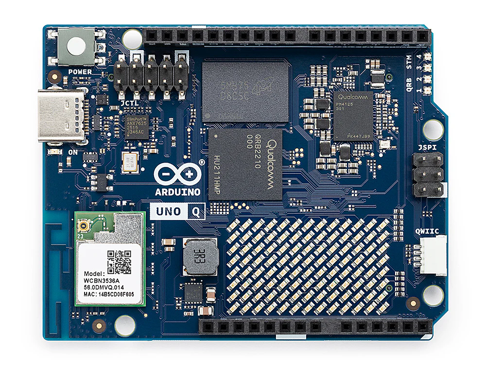
Arduino UNO Q. The JCTL debug header sits at the upper left, next to the USB-C port; the QRB2210 and the WCBN3536A radio module are labelled on the board. Photo: Arduino via Wikimedia Commons, CC BY 3.0.

Authoritative hardware reference: https://docs.arduino.cc/hardware/uno-q/. The notes below cover a quick start and the details that matter for building your own Linux image; for pinouts, mechanical layout, and silicon details, defer to Arduino’s documentation.
Getting a terminal
adb shell over USB-C
This is the everyday path, and the one to reach for first. The stock image runs an ADB daemon exposed over the USB-C data port, so a shell is one command away:
adb devices
adb shell
Install adb from your distribution (android-tools on Alpine and Arch,
android-tools-adb on Debian and Ubuntu). On Linux you also need a udev rule so
the device is reachable without root; Arduino’s documentation covers the rule
set for the board’s USB IDs.
adb gives you a shell, file transfer (adb push / adb pull), and port
forwarding — including the forward used to debug the STM32U585 (see
The real-time brain below). What it does not give you is
anything before userspace comes up: no bootloader prompt, no kernel log from a
boot that fails early, and no way in when networking or the ADB daemon itself is
broken. That is what the serial console is for.
Serial console on the JCTL connector
The QRB2210’s console UART is brought out on the 10-pin JCTL header (A1 /
JCTL1), which also carries the board’s boot-mode, reset, and low-power wake
signals. The console is the SoC’s SE4 UART, which appears in Linux as
ttyMSM0 at 115200 8N1, no flow control. Arduino reserves SE4 as the system
console — it is separate from the application UARTs and should not be
repurposed.
JCTL pinout
| Pin | Designation | Net / function | Domain | Notes |
|---|---|---|---|---|
| 1 | GND | Ground | Power | — |
| 2 | USB_BOOT | Boot strap | 1.8 V | Forced USB boot (EDL) |
| 3 | VOL_DOWN | GPIO_36 | 1.8 V | GPIO |
| 4 | SOC_SE4_TX | Console UART TX (SE4) | 1.8 V | System console |
| 5 | VOL_UP | GPIO_96 | 1.8 V | GPIO |
| 6 | SOC_SE4_RX | Console UART RX (SE4) | 1.8 V | System console |
| 7 | GND | Ground | Power | — |
| 8 | PMIC_RESET | PM4125 reset | 1.8 V | — |
| 9 | +1V8 OUT | VREG_L15A_1P8V | Power | 1.8 V reference |
| 10 | VBUS_DISABLE | VBUS power-switch disable | 1.8 V | Controls the VBUS path |
Source: UNO Q datasheet, §9.5.
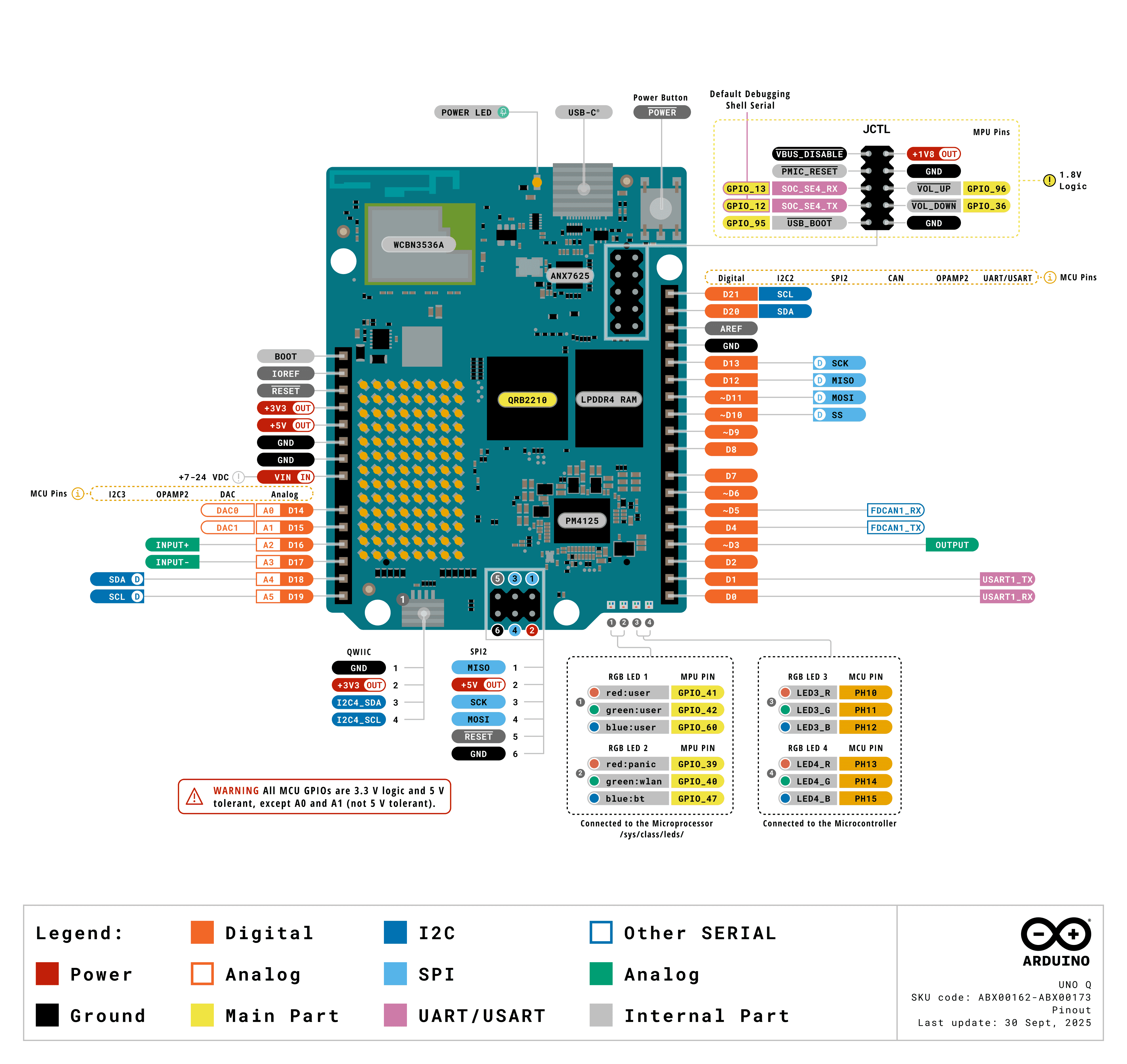
The full UNO Q pinout. The JCTL header is at the upper right; the “Default
Debugging Shell Serial” callout marks SOC_SE4_RX / SOC_SE4_TX, and the whole
header is flagged 1.8 V Logic. Image:
Arduino.
The signals are 1.8 V, not 3.3 V. A standard 3.3 V USB-TTL adapter — the kind that works on a BeaglePlay or a Raspberry Pi — can damage the SoC here. Use a 1.8 V-capable adapter, or one with a selectable
VCCIOreference you can tie to pin 9. Verify the level before connecting anything.
Choosing an adapter
- Recommended: Arduino BugHopper (product page · datasheet). Purpose-built for this board’s JCTL connector: a USB-C to UART bridge (FTDI FT230XQ) on a 1.27 mm 2×5 header that matches the JCTL pitch, so it mates directly with no jumper wires and derives its logic level from the target. This is the path of least resistance, and it removes any chance of putting a 3.3 V signal on a 1.8 V pin.
- Generic alternative: DSD TECH SH-U09C2
(Amazon).
A USB-to-TTL adapter built on a genuine FTDI FT232RL, with the logic level
jumper-selectable between 1.8 V, 3.3 V, and 5 V — set the jumper to 1.8
V before connecting anything to the JCTL header. The FTDI silicon means the
host’s
ftdi_siodriver picks it up cleanly. Wire onlyGND/RX/TXper the table below and leave the rest disconnected.
With a jumper-wired adapter, three wires are enough for a console:
| JCTL pin | Adapter |
|---|---|
1 or 7 (GND) | GND |
4 (SOC_SE4_TX) | RX |
6 (SOC_SE4_RX) | TX |
Wiring follows the usual cross-over: the board’s TX goes to the adapter’s RX,
and vice versa. Leave the adapter’s supply lead disconnected — the board has its
own power. Pin 9 is an output, so use it only as a VCCIO reference for a
level-shifting adapter, never as a supply to drive the board.
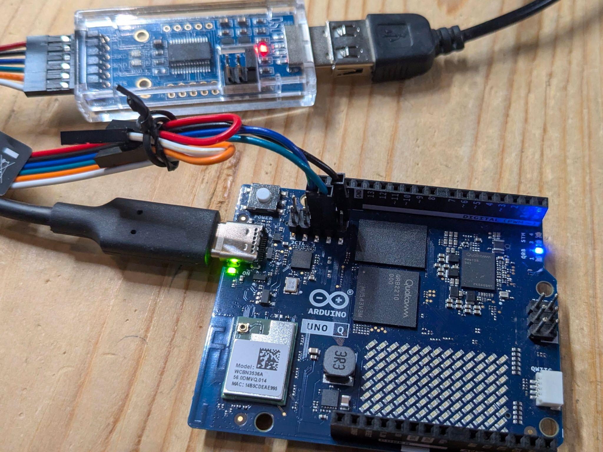
A jumper-wired console on the UNO Q. The SH-U09C2 adapter is at the top left,
with its level-select jumper on the board next to the USB connector — set that
to 1.8 V before making any connection. Only the GND, RX, and TX leads
reach the JCTL header just above the QRB2210; the remaining leads are tied back
and left unconnected. The board takes its own power from the USB-C port on the
left, so the adapter’s supply lead stays out of the circuit.
Once wired, the adapter enumerates on the host as /dev/ttyUSB0 (FTDI, CP210x,
CH340) or /dev/ttyACM0 (CDC ACM). Open it with
tio, which defaults to 115200 8N1:
tio /dev/ttyUSB0
If nothing appears after power-on:
- Swap RX and TX. This is the most common mistake.
- Confirm the adapter is running at 1.8 V.
- Check
dmesg | tailon the host — the adapter should enumerate within a second or two of being plugged in. If it does not, the problem is the cable, not the board.
Boot chain
The QRB2210 boots through Qualcomm’s standard multi-stage chain, with U-Boot taking the place of Qualcomm’s Android bootloader as the final firmware stage. U-Boot presents itself as UEFI firmware rather than using its own boot commands, so the tail of the chain is a conventional UEFI Linux boot:
PBL (masked ROM)
  └── XBL                             ← Qualcomm firmware, signed
        └── TrustZone / RPM / Hypervisor
              └── U-Boot              ← in the abl slot; presents UEFI 2.11
                    └── systemd-boot  ← ESP:/EFI/BOOT/BOOTAA64.EFI
                          └── Boot Loader Specification type#1 entry
                                └── vmlinuz + initrd
                                      └── init
On a stock board this reports itself as Das U-Boot 8230.256 providing
UEFI 2.110, chainloading systemd-boot 257.8.
Three consequences matter when building images for this board:
- The kernel is selected by a BLS entry, not a boot script. Entries live in
loader/entries/<machine-id>-<version>.confon the ESP, with the kernel and initrd under<machine-id>/<version>/. Debian’s stockkernel-installhooks generate all of this on a running system. Multiple kernel generations coexist, each with its own entry, which gives rollback for free. - The device tree comes from U-Boot, not from the BLS entry. There is no
devicetreeline in the entry. U-Boot loads/boot/efi/dtb/qcom/qrb2210-arduino-imola.dtboff the ESP, which is what makes the carrier-board overlay mechanism below work. - The GPT is large and mostly firmware. The table has 69 entries, of which a
Linux image owns three. Partition 67 is the EFI system partition mounted at
/boot/efi, 68 is the rootfs, and 69 isuserdata, mounted at/home/arduino. An image replaces the tail of the table, not the whole thing. The partition table section below accounts for the other 66.
Because the rootfs partition sits mid-table with a populated userdata
partition behind it, ordinary first-boot resize tooling tends to misbehave — it
expects free space after the filesystem it is growing. Expect to need a resize
step that understands this layout, or to size the rootfs correctly up front.
The partition table: why 69?
The layout is not Arduino’s. It is Qualcomm’s stock reference table for this SoC
family, inherited from the Android device model; Arduino swapped only the tail,
where an Android device carries system / vendor / product. Everything
ahead of partition 67 is as Qualcomm ships it, which is why the board looks
nothing like a two-partition SD-card target.
The count breaks down as 19 A/B pairs (38 partitions) plus 31 single-copy partitions.
Why so many firmware partitions. The QRB2210 does not have “a bootloader.” It has a chain of independently signed images, several of which run on different processors — the RPM is its own Cortex-M, TrustZone runs at EL3, and the modem and ADSP are separate DSPs. Each image is separately authenticated and separately updatable, so each gets a partition:
xbl, xbl_config, tz, rpm, hyp, abl, uefi, uefi_dtb, devcfg,
qupfw, ddr, imagefv, featenabler, keymaster, uefisecapp, mdtp,
mdtpsecapp, multiimgoem, boot
A few are less self-explanatory than the rest: ddr holds DDR training
parameters, qupfw the QUP serial-engine firmware, keymaster and uefisecapp
are TrustZone trusted applications, and devcfg is per-device hardware
configuration consumed very early in the chain. Each of these 19 is then doubled
_a/_b for seamless update and rollback — the mechanism behind the
A/B slot blessing
requirement below.
Why the 31 singletons are not duplicated. They hold per-device state that must survive a reflash:
| Group | Partitions |
|---|---|
| Modem NV and calibration | modemst1, modemst2, fsg, fsc, persist |
| Device identity, security | devinfo, secdata, storsec, keystore, frp, ssd, dip, apdp |
| Boot control and recovery | misc, misc_boot, recoveryinfo, cateloader, catefv, catecontentfv, toolsfv, multiimgqti |
| Diagnostics | rawdump, logfs, logdump, limits (thermal) |
| Firmware-owned state | uefivarstore, spunvm, splash |
| The OS | efi, rootfs, userdata |
misc is the bootloader control block — the conventional way a running system
asks the firmware to boot into fastboot on the next reset.
There are more than 69. Those are the GPT on the eMMC’s user area. The eMMC
also exposes two hardware boot areas with their own tables, carrying five
further labelled regions: bdaddr, wlanaddr, and a second persist on
boot0, plus CDT and last_grow on boot1. The Bluetooth and WLAN MAC
addresses live there, along with the Configuration Data Table that XBL reads
before DDR is trained. They sit in write-protectable areas precisely because
they are per-unit identity rather than software.
Why this shapes everything else. yoe cannot own this table. 38 partitions
hold signed blobs it does not build, and 28 more hold state whose loss would
cost the board its MAC addresses, modem calibration, or thermal limits. Writing
efi and rootfs and leaving the rest untouched is the only sane posture —
which is what the machine descriptor’s two-partition model and the
--allow-missing flash invocation encode.
A/B slots: a boot is provisional until userspace says otherwise
Every partition in the boot chain is paired (xbl_a/xbl_b, abl_a/abl_b, …
— the 19 bases listed above), and the Qualcomm boot firmware treats each boot as
provisional. Userspace has to mark the slot good, or the firmware exhausts its
retry count, switches to the other slot, and the board stops booting.
On a stock board qbootctl reports slot _a as
Active 1 / Successful 1 / Bootable 1 and _b as Successful 0; that
Successful flag is what the marking sets. It also notes that the cmdline
carries no androidboot.slot_suffix, so it reads the active slot from the
control block instead — a custom cmdline does not need to supply one.
qbootctl does that marking. Its service runs qbootctl -m after
boot-complete.target; Debian ships the package in trixie/main and its
postinst enables the service. The arduino-uno-q machine therefore carries
qbootctl as a board-essential package, alongside the firmware.
This failure mode is worth internalizing before building a custom image: it does
not appear on the boot that caused it. An image missing qbootctl comes up
fine, works normally, and then stops booting several reboots later — which
presents as a hardware brick rather than a packaging mistake. Recovery is EDL,
so it is recoverable, but the diagnosis is not obvious.
Carrier boards and device-tree overlays
The board composes its device tree at runtime rather than shipping one DTB per
hardware combination. arduino-linux-config carrier enable … merges the
selected .dtbo overlays onto qrb2210-arduino-imola-base.dtb with
fdtoverlay and writes the result to qrb2210-arduino-imola.dtb, taking effect
on the next boot. Overlays exist for the media carrier, IMX219 cameras on either
CSI port at two or four lanes, and 5/8/10-inch DSI touch panels.
Pending state is kept in /var/lib/arduino-linux-config/status, which is why
carrier show reports [current: …] and [next: …] separately. One image
therefore serves every carrier, camera, and panel combination — the variation is
resolved at runtime, with no per-carrier build fork.
Flashing a Linux image
The board flashes over EDL (Emergency Download Mode), Qualcomm’s ROM-level
recovery protocol, using the qdl tool. There is no removable boot medium — the
eMMC is the only boot storage, so EDL is both the normal install path and the
unbrick path.
Entering EDL mode
- Power the board off completely — disconnect USB-C.
- Place a jumper across JCTL pins 1 and 2 —
GNDandUSB_BOOT. Tying the boot strap low is what forces the ROM into USB download mode. The two pins sit at one end of the header, so a plain 2.54 mm jumper shunt works. - Connect USB-C to the host.
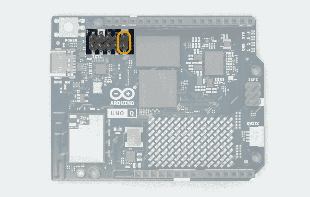
The two JCTL boot-strap pins to jumper for EDL, highlighted in orange. Image: Arduino.
The board should now enumerate as 05c6:9008 (Qualcomm HS-USB QDLoader 9008).
Confirm with lsusb. If you see the normal ADB device instead, the jumper is
not making contact or the board was not fully powered down.
Host setup
yoe flash supplies its own qdl — a version-pinned unit that runs inside a
container, so nothing needs installing on the host beyond the container runtime
yoe already requires. What follows applies when driving qdl by hand; the udev
rule and the ModemManager note apply either way.
Install qdl from your distribution — Debian and Ubuntu package the upstream
linux-msm/qdl as qdl:
sudo apt install qdl
Stop ModemManager before flashing. It claims the 05c6:9008 device and
makes the flash fail in ways that look nothing like the cause:
sudo systemctl stop ModemManager
qdl needs raw USB access. Without a udev rule you will see
qdl: unable to open USB device. Create
/etc/udev/rules.d/51-arduino-uno-q.rules:
SUBSYSTEM=="usb", ATTR{idVendor}=="05c6", ATTR{idProduct}=="9008", MODE="0666", GROUP="plugdev"
Then reload:
sudo udevadm control --reload-rules && sudo udevadm trigger
Writing a stock Arduino image
Arduino’s arduino-flasher-cli wraps the whole flow, including fetching the
image:
./arduino-flasher-cli flash latest
To drive qdl directly against an unpacked image directory:
cd arduino-images/flash
qdl --allow-missing --storage emmc prog_firehose_ddr.elf rawprogram0.xml patch0.xml
prog_firehose_ddr.elf is the signed programmer the ROM loads first; the
rawprogram*.xml and patch*.xml files describe the partition table and the
images that fill it. --allow-missing lets a partial image set flash without
every firmware partition present.
Writing a yoe image
yoe flash drives qdl for this machine rather than writing to a block device.
The board must already be in EDL:
yoe flash dev-image --programmer /path/to/prog_firehose_ddr.elf
yoe writes only the two partitions it owns — efi and rootfs. Vendor firmware
and userdata are left untouched, so a reflash preserves /home/arduino. The
confirmation prompt names the partitions before anything is written; --yes
skips it and --dry-run reports what would happen.
The programmer is a signed vendor blob and is not redistributed with yoe. Point at a copy from Arduino’s image bundle.
Updating a running board without reflashing
Reflashing is for when the rootfs changes shape. For package-level change,
yoe deploy installs a unit onto a running board over SSH:
yoe deploy my-unit bec-uno-q.local
That is a seconds-long loop against a multi-gigabyte rootfs rewrite, and it does not need EDL, a jumper, or a power cycle.
Afterwards
Remove the JCTL jumper and power-cycle the board. Leaving the jumper in place sends it straight back into EDL on the next boot, which reads as “the board no longer starts.”
Keep a known-good stock image on hand. Because EDL lives in masked ROM, a bad Linux image is always recoverable — but only if you have something to flash back.
The yoe BSP for this board
Board support lives in module-qcom, which is named for the SoC vendor
rather than the board — Qualcomm’s own RB1/RB2 and Arduino’s sibling Ventun Q
would reuse most of it.
The board runs stock Debian trixie. Everything board-specific comes from one
small vendor apt repo, apt-repo.arduino.cc, wrapped as a single feed:
| Piece | Where it comes from |
|---|---|
| Rootfs | Debian trixie, via @module-debian’s feeds |
| Kernel + device tree | linux-image-7.0.0-g122c2c22d838 from the vendor feed, carrying qrb2210-arduino-imola* |
| Qualcomm firmware | firmware-qcom-soc (Debian non-free-firmware) — adsp, modem, wlanmdsp, GPU zap |
| Wi-Fi / BT firmware | firmware-atheros, plus arduino-unoq-radio-firmware for per-PCB board data |
| Carrier overlays | arduino-linux-config |
| Audio | alsa-ucm-conf, vendor-patched for the QRB2210 audio path |
| A/B slot blessing | qbootctl (Debian main) — see above; omitting it eventually stops the board booting |
| Boot firmware | Factory-provisioned; yoe does not build or write it |
The machine descriptor is machines/arduino-uno-q.star. It models the two
partitions yoe owns — efi (vfat, 512M) and rootfs (ext4, 10G) — at the
factory GPT’s sizes, so each partition image can be written straight into its
slot. userdata is deliberately absent: it holds user data and is meant to
survive a reflash, so it is provisioned once and never image content.
Two kernel command-line arguments are mandatory rather than tuning:
clk_ignore_unused and pd_ignore_unused. TrustZone and the always-on firmware
hold clocks and power domains the kernel cannot refcount, and gating them at
late_initcall hangs the board.
The machine pins the kernel package by its exact versioned name, because the
vendor feed publishes no linux-image-arm64-style metapackage to track instead.
A kernel bump changes that name, so yoe update-feeds in module-qcom and the
machine descriptor move together.
Debian images only
The kernel and every board package come from a Debian-format feed, so this
machine boots Debian and nothing else. Its kernel(distro_unit = {"debian": …})
says so, and that declaration is what the rest of yoe reads: images targeting
any other distro are marked not buildable on this machine rather than resolved.
A project selecting arduino-uno-q may therefore still load @module-alpine
and any other module that defines images for other distros — those images
register inert and evaluation succeeds. Building one by name is refused with the
reason; a build that names no target skips them with a notice and builds the
rest. See
distro.md.
One consequence worth knowing: a project whose defaults.distro is not debian
needs --distro debian (or a local.star override) when building for this
board, or its images evaluate for the wrong distro and get marked:
yoe build --machine arduino-uno-q --distro debian base-image
Mainline
Mainline Linux support for the QRB2210 is progressing — the SoC boots to a login
shell on recent mainline kernels using the qrb2210-rb1 device tree, with GPU
and Bluetooth held back pending firmware packaging. Tracking mainline rather
than a vendor branch is the preferable target once the gaps close, and it would
remove the versioned-kernel-package pin above.
The real-time brain
The STM32U585 runs Zephyr, and the QRB2210 acts as its SWD debug adapter through
an openocd binary on the board. From a host with adb:
adb forward tcp:3333 tcp:3333
adb shell arduino-debug
That exposes OpenOCD on the host’s port 3333, so a normal Zephyr workflow applies:
west build -b arduino_uno_q samples/basic/blinky
Internal UART and SPI buses connect the two processors, which is how application code on the MCU reaches the Linux side. Zephyr’s board documentation is the reference here: https://docs.zephyrproject.org/latest/boards/arduino/uno_q/doc/index.html.
References
- UNO Q product documentation — Arduino
- UNO Q user manual — pinout, JCTL, ADB setup
- UNO Q datasheet (ABX00162 / ABX00173) — connector pin maps, power domains
- Arduino UNO Q in Zephyr
- Armbian UNO Q support — boot chain, partition layout, qdl flow
- Arduino BugHopper — JCTL debug adapter (datasheet)
- DSD TECH SH-U09C2 — FTDI USB-to-TTL adapter, jumper-selectable 1.8 / 3.3 / 5 V (Amazon)