BeaglePlay BSP
This page documents the BeaglePlay board support in yoe: which units make up the BSP, how they cooperate at build time, and how the resulting artifacts are arranged on the SD card or eMMC.
The hardware is BeagleBoard.org’s BeaglePlay, built on TI’s AM625 SoC (quad Cortex-A53 application cores, a Cortex-R5F MCU island, and a Cortex-M4F dead-man core). The cores run with help from TI’s K3 security firmware (“TIFS” / “SYSFW”) and a small device-manager (“DM”) payload — both shipped as signed blobs by TI.
The machine descriptor lives at modules/module-bsp/machines/beagleplay.star;
everything below is built by units under modules/module-bsp/units/bsp/.
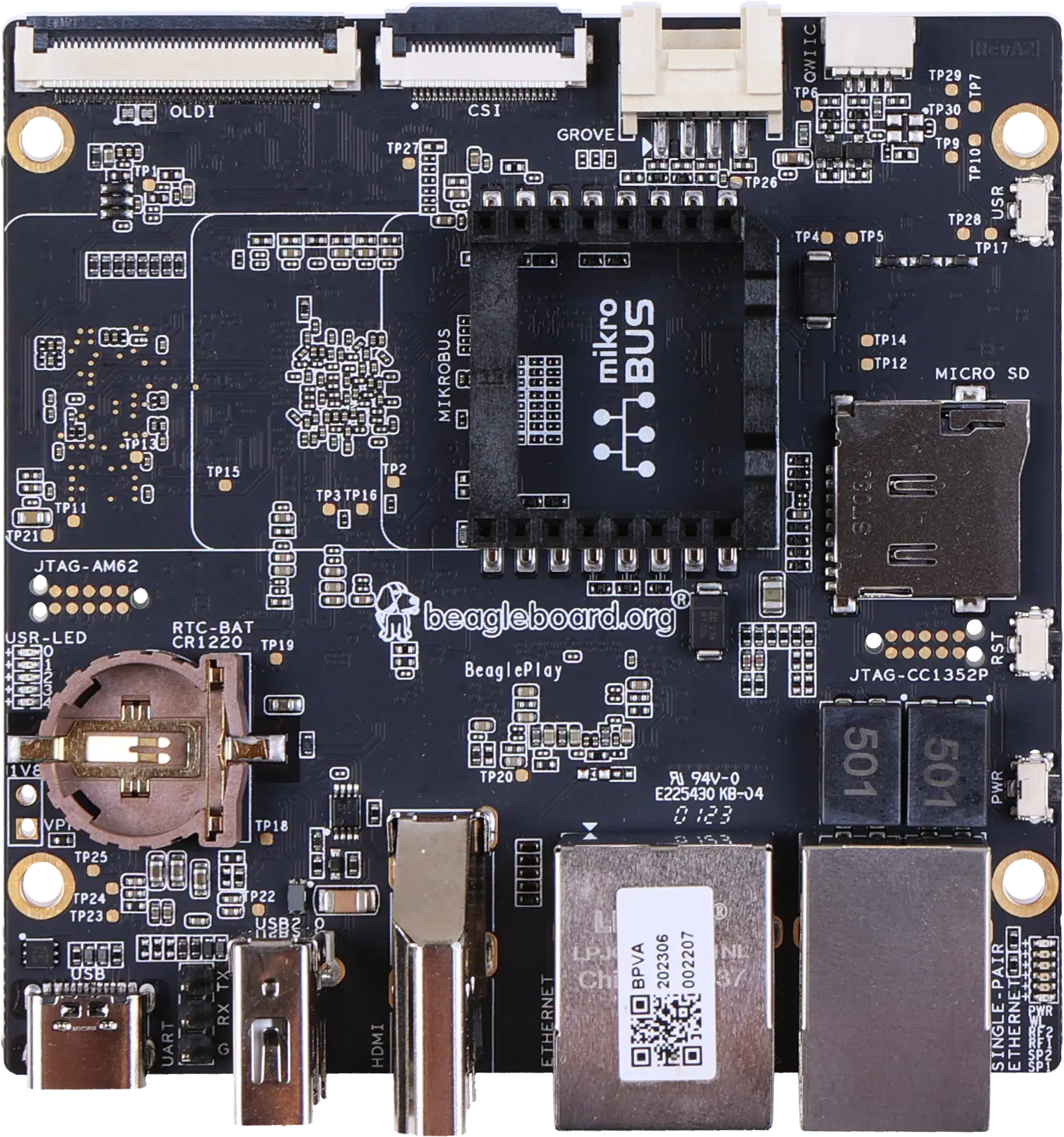
Photo: BeagleBoard.org, CC BY-SA 4.0.
Running it on hardware
After yoe build --machine beagleplay base-image (or whatever image you’ve
picked), yoe produces a single disk image under
build/<image>.beagleplay/disk.img (the exact path depends on the image’s
disk task). The next steps are: write it to a microSD card, connect serial
- power, and power on.
Authoritative hardware reference for everything below: https://docs.beagleboard.org/boards/beagleplay/. The notes here cover the yoe-specific bits and a quick start; for pinouts, mechanical layout, and silicon details, defer to BeagleBoard.org’s docs.
Writing the image to a microSD card
Two ways:
-
TUI — open
yoe(no arguments), highlight the image unit, pressf. The flash UI shows the candidate removable devices and you pick one. This is the fast path during development. -
CLI —
yoe flash <image-unit> <device>. List candidates first:yoe flash listThat prints the
/dev/sdN(or/dev/mmcblkN) entries with size and model so you can identify the card. Then write:yoe flash --machine beagleplay base-image /dev/sdNSwap
base-imagefor whichever image unit you built (jukebox-image, your own, …).--dry-runshows what it would do without touching the device;--yesskips the confirmation prompt for scripted flows.
Either path picks the right disk image from the build tree, refuses to write to anything mounted or anything that looks like an internal disk, and confirms before overwriting. If a partition on the target is mounted (most desktops auto-mount removable media on insert), the flash exits with a message — unmount the partitions and retry. Read the device path it’s about to write to; flashing the wrong block device will silently overwrite it.
Choosing boot media (SD vs eMMC)
The AM625 ROM checks boot sources in a sequence set by the SYSBOOT straps on the board. On BeaglePlay the default boot order looks at the on-board 16 GB eMMC first.
To boot from microSD instead, hold the USR button while applying power or
pressing reset. That overrides the ROM’s boot search to start at the SD slot.
Release the button once you see the SPL banner on the serial console (~1
second). The override is per-boot — power-cycling without the button reverts to
eMMC.
For development you typically want microSD boot: it’s easy to re-flash, hard to brick, and leaves the eMMC’s contents alone. For production you’d flash a known image into eMMC (either by booting an SD-based installer or over USB-DFU) and ship without an SD card.
The yoe image is identical for both paths — the boot chain on eMMC and on SD
comes from the same tiboot3.bin / tispl.bin / u-boot.img artifacts. yoe’s
uEnv.txt hardcodes root=/dev/mmcblk1p2 (eMMC); if you boot off SD without
re-flashing eMMC, the kernel will still try to mount the eMMC’s rootfs. Either
flash both, or edit bootargs to root=/dev/mmcblk0p2 for SD-only.
Power
BeaglePlay takes 5 V over USB-C on the dedicated power connector. A phone-class 5 V / 1 A supply is enough for the board itself idling. Plan for at least 3 A in practice — a class-compliant USB-C charger (a laptop / phone charger that negotiates 5 V / 3 A) is the cheapest path. Underpowering shows up as kernel crashes during DRAM stress, WiFi disconnects under load, or the board silently rebooting once anything is plugged into USB.
The power connector is not the same physical port as the debug serial-USB. Read the silkscreen.
Serial console
The kernel and U-Boot both use the SoC’s UART0 (Linux ttyS2) at 115200
8N1, no flow control. This is the same setting uEnv.txt expects and what
am62xx.inc upstream uses, so any client targeting “BeaglePlay serial console”
will be at 115200 by default.
BeaglePlay does not have an on-board USB-to-serial bridge. The debug UART is
brought out on a 3-pin header wired in the Raspberry Pi USB-to-TTL serial
cable pinout — the same GND / RXD / TXD layout the standard Pi debug
cables use. You’ll need an external adapter:
- Recommended: FTDI TTL-232R-RPi
(product page ·
Digi-Key).
Purpose-built for the Pi-style header, 3.3 V signals, genuine FTDI silicon (so
the host’s
ftdi_siodriver picks it up reliably and you don’t fight knock-off CP210x / CH340 driver quirks). Plug-and-play with no wiring decisions. - Any other 3.3 V USB-TTL adapter (Adafruit 954, generic FTDI/CP210x/CH340 dongles) works too — connect three jumpers, leave the 5 V lead disconnected since the board has its own power.
Wiring is “cross-over”: the cable’s TX goes to the board’s RX, and vice
versa. GND to GND. Check the silkscreen on the BeaglePlay header for RX /
TX markings — those refer to the board’s signals.
Once wired, plug the USB end into the host; it enumerates as /dev/ttyUSB0
(FTDI / CH340 / CP210x) or /dev/ttyACM0 (some CDC ACM adapters). Open it with
tio, which defaults to 115200 8N1:
tio /dev/ttyUSB0
If nothing appears after power-on:
- Swap RX/TX. The single most common mistake.
- Confirm the adapter is 3.3 V, not 5 V. A 5 V adapter on the AM625’s UART pins is the fastest way to brick the SoC’s UART block.
dmesg | tailon the host — the USB-TTL adapter should enumerate within a second or two of plugging in. If it doesn’t, the cable / dongle is the issue, not the board.
First boot
A successful boot prints (roughly, abbreviated):
U-Boot SPL 2025.10 ...                  ← R5 SPL (from tiboot3.bin)
Trying to boot from MMC1                 ← reading tispl.bin
U-Boot SPL 2025.10 ...                  ← A53 SPL (from tispl.bin)
NOTICE:  BL31: ...                       ← TF-A handoff
I/TC: OP-TEE version: 4.9.0 ...          ← OP-TEE handoff
U-Boot 2025.10 ...                       ← U-Boot proper
Hit any key to stop autoboot:
...
Booting Linux on physical CPU 0x...      ← kernel
...
Welcome to <hostname>
<hostname> login:
The default credentials from base-files-* are root (no password) and user
/ password. Change them before connecting the board to any network you don’t
fully control — the OpenSSH unit defaults to enabled once the package lands in
the image.
If the boot stops at U-Boot’s Hit any key prompt and never autoboots, either
uEnv.txt wasn’t found on the boot partition, or uenvcmd failed mid-way. Drop
to the U-Boot shell, ls mmc 1:1 to see what’s on the FAT partition, and re-run
the load commands one by one to see which one errors.
Analog input
BeaglePlay’s only analog inputs come from an on-board ADC102S051 — a two-channel
10-bit SPI ADC sitting on the SoC’s MCU_SPI1 bus at chip select 1. Channel 0
reaches the mikroBUS AN pin; channel 1 reaches the Grove connector’s analog
pin. Both accept 0–3.3 V, referenced to the board’s vdd_3v3 rail. Do not
exceed 3.3 V — the only thing between a connector pin and the ADC is a 1 kΩ
series resistor and a 100 pF cap (and, on the Grove pin, a ferrite bead and an
ESD clamp). That is an anti-alias filter and an ESD part, not overvoltage
protection.
Finding the pins
Hold the board the way BeagleBoard.org photographs it: USB-C, HDMI and the two
Ethernet jacks down the left edge, the expansion connectors down the right edge,
the mikroBUS silkscreen logo reading upright. Both analog inputs are then on
the right-hand half of the board.
      ┌───────────────────────────────────────────┐
      │  o                                     o  │
 USB-C┤                                           ├ OLDI
  UART┤                ┌───────────────┐          │
 USB-A┤                │               │          ├ CSI2
  HDMI┤                │   mikroBUS    │          │
      │                │    socket     │          ├ GROVE  ← analog
   Eth┤                │               │          │
   SPE┤                └───────────────┘          ├ QWIIC
      │        [ microSD ]                        │
      │  o                                     o  │
      └───────────────────────────────────────────┘
mikroBUS AN is the top pin of the socket’s left-hand row — the corner
nearest the CSI2 connector, diagonally opposite the two ground pins. Pin numbers
below are the board schematic’s (J21); the names are the mikroBUS standard’s.
                ┌────────────────────────────┐
  ADC ch 0 →  9 │ ● AN              PWM ●  8 │
             10 │ ● RST             INT ●  7 │
             11 │ ● CS               RX ●  6 │
             12 │ ● SCK              TX ●  5 │
             13 │ ● MISO            SCL ●  4 │
             14 │ ● MOSI            SDA ●  3 │
             15 │ ● +3V3            +5V ●  2 │
             16 │ ● GND             GND ●  1 │
                └────────── mikroBUS ────────┘
Grove’s analog pin is pin 1, the one the silkscreen triangle points at and
the one nearest CSI2. It is a 4-pin JST 2.0 mm right-angle header (J7), wired
to the Grove standard’s order:
            ┌──────────────┐
   ▲   1 ●  │  SCL / AIN   │ ← ADC ch 1
       2 ●  │  SDA         │
       3 ●  │  3V3         │
       4 ●  │  GND         │
            └── GROVE ─────┘
Each pin has a second job
Neither analog pin is analog-only, and that matters more on Grove than on mikroBUS:
mikroBUS AN (J21 pin 9)                          ADC102S051 (U11)
  ├── GPIO1_10 ......... main_gpio1 line 10      ┌─────────────────┐
  └── AIN1 ─ R68 1kΩ ─┬─────────────────────────►│ IN1 (pin 5)     │  in_voltage0
                      └── C235 100pF ── GND      │                 │
                                                 │                 │
Grove pin 1 (J7), behind ferrite bead FB27       │                 │
  ├── D20 ESD clamp ── GND                       │                 │
  ├── I2C1_SCL ......... /dev/i2c-1              │                 │
  └── AIN2 ─ R67 1kΩ ─┬─────────────────────────►│ IN2 (pin 4)     │  in_voltage1
                      └── C234 100pF ── GND      └─────────────────┘
                                                  VA = 3.3 V reference
On mikroBUS this is harmless: the device tree muxes AN as GPIO1_10
(MIKROBUS_GPIO1_10 in gpio-line-names) with the pad configured as a plain
high-impedance input, so nothing drives the pin and the ADC sees whatever the
click board puts there.
On Grove it is not. The same pin is I2C1_SCL, the device tree enables
main_i2c1 on it as /dev/i2c-1, and the pad is muxed PIN_INPUT_PULLUP. So
the pin idles pulled high — in_voltage1_raw on an otherwise idle bus reads
near full scale, not zero — and any I²C traffic on that bus shows up as noise in
the samples. Treat the Grove connector as either an I²C port or an analog input,
not both at once; if you want a quiet analog channel there, take main_i2c1 out
of the device tree.
The kernel exposes it through the industrial I/O (IIO) subsystem:
# cat /sys/bus/iio/devices/iio:device0/name
adc122s051
# cat /sys/bus/iio/devices/iio:device0/in_voltage_scale
0.805664062
# cat /sys/bus/iio/devices/iio:device0/in_voltage0_raw
2380
Multiply a channel’s _raw by the scale to get millivolts, so the reading above
is 1917 mV. Note that the scale attribute is in_voltage_scale, without a
channel index — the driver shares one scale across both channels rather than
publishing in_voltage0_scale and in_voltage1_scale separately.
The scale is a 12-bit figure because the driver binds the part as its 12-bit
sibling (see below); the hardware really is 10-bit, so the two low bits of every
reading come back zero. Note also that an unconnected mikroBUS AN pin floats
rather than reading zero — expect noise on a channel with nothing wired to it.
The Grove channel behaves differently for the reason given above: it idles high,
not floating.
The driver is a module, and the SPI controller it hangs off is built into the
kernel — the controller registers the ADC during early boot, before any
userspace exists to see the uevent. Two things make it load anyway.
beagleplay-config ships /usr/lib/modules-load.d/beagleplay-adc.conf naming
ti-adc128s052, which OpenRC’s modules service (and systemd-modules-load on
the Debian and Ubuntu images) processes at boot; the ADC is soldered to the
board, so naming it outright is the most direct thing to do and it holds even in
an image that carries no coldplug. Separately, the general mechanism described
under
Coldplug
would find this chip too, along with anything else plugged in.
For anything beyond reading raw counts, use libiio, which the development
image already carries: iio_info enumerates every device, channel and attribute
in one shot, iio_attr reads and writes them by name, and iio_readdev streams
sample buffers. To work with the board’s sensors from a development host
instead, add the iiod-init package — it runs the IIO network daemon, and it is
a separate package because that daemon has no authentication and grants any
client on the network read and write access to these channels.
Both connectors are documented, with schematics, on BeagleBoard.org’s BeaglePlay design page; the pin numbers and net names above come from those schematics.
The device tree names the part ti,adc122s051 rather than ti,adc102s051. The
driver (drivers/iio/adc/ti-adc128s052.c) carries only the 12-bit variants —
the 10-bit compatible strings that older kernels listed were removed upstream.
The parts are protocol compatible and the 10-bit result arrives left-aligned in
the 12-bit frame, which is why the 12-bit scale is the correct one to apply.
Boot chain at a glance
The AM625 boot ROM expects a multi-stage handoff. Each blob feeds the next, and most of the blobs are themselves FIT images that bundle code from several upstream projects.
ROM (AM625)
  └── tiboot3.bin                  ← U-Boot R5 SPL + TIFS + DM
        └── tispl.bin              ← U-Boot A53 SPL + BL31 (TF-A) + BL32 (OP-TEE) + DM
              └── u-boot.img       ← U-Boot proper (A53)
                    └── Image      ← Linux kernel (arm64) + DTB
                          └── init ← OpenRC (busybox PID 1)
Each arrow is “loads and jumps to”. Two CPU clusters take turns: the R5F brings the secure firmware up first, then hands the SoC over to the A53s for the rest of the chain.
The units
| Unit | Produces | Stage | Notes |
|---|---|---|---|
ti-linux-firmware | /lib/firmware/{ti-sysfw,ti-dm,...}/ | binman input | TI blobs, no compile |
u-boot-beagleplay-r5 | boot/tiboot3.bin | ROM → | R5F SPL, embeds TIFS + DM |
tfa-k3 | /lib/firmware/bl31.bin | binman input | EL3 secure monitor |
optee-k3 | /lib/firmware/bl32.bin | binman input | Trusted Execution Environment |
u-boot-beagleplay | boot/tispl.bin, boot/u-boot.img | tiboot3 → | A53 SPL + U-Boot proper |
linux-beagleplay | boot/Image, boot/k3-am625-beagleplay.dtb, kernel modules | u-boot.img → | Beagle’s 6.12 fork |
beagleplay-config | boot/uEnv.txt | u-boot reads | bootargs + boot script |
Sources and pinning:
ti-linux-firmware—git://git.ti.com/...branchti-linux-firmware, prebuilt blobs only. Cadence/PRU/etc. also ship through this unit so other rootfs units can pick what they need without re-cloning.tfa-k3—git.trustedfirmware.org/TF-Amaster. K3 platform support lives only on master (no per-release tag), and meta-ti pins to a master SRCREV; we follow the same branch so future syncs roll forward.optee-k3— upstreamOP-TEE/optee_osat tag4.9.0, mirroring meta-ti’soptee-os-ti-version.inc.u-boot-beagleplay/u-boot-beagleplay-r5— both build fromgithub.com/beagleboard/u-bootbranchv2025.10-Beagle. Same tree, two defconfigs (_a53_and_r5_), so they share the dep chain for build tools.linux-beagleplay—github.com/beagleboard/linuxbranchv6.12.43-ti-arm64-r54, the AM625 device tree + cape overlays that meta- beagle ships.beagleplay-config— local Starlark, generatesuEnv.txtonly.
All units build in the generic toolchain container with
container_arch = "target" — the resolver dispatches that to the toolchain
matching the image’s distro (Alpine’s musl toolchain for an Alpine image, the
glibc toolchain for Debian/Ubuntu), all running aarch64-native under QEMU
user-mode. There is no cross-compilation in the conventional sense — the build
sees the target ISA as native. The firmware these units emit is freestanding, so
it is identical regardless of which distro’s toolchain compiled it; the board
boots the same image on any backend. Build-time tools whose package names differ
across backends (Alpine’s py3-* vs the apt distros’ python3-*, bundled
-dev headers vs split lib*-dev) are expressed with distro_deps so each
backend pulls its own names. The R5 SPL is the one exception to “native”:
Cortex-R5F is armv7-R, an ISA the aarch64 toolchain can’t emit, so it pulls a
bare-metal gcc-arm-none-eabi cross toolchain from the build distro’s own feed.
Stage-by-stage walkthrough
Stage 0: ROM
The AM625 ROM is masked silicon. On power-up it reads tiboot3.bin from the
configured boot media (SD MMC0 / eMMC MMC1 / OSPI, selected by SYSBOOT straps).
The file is a FIT image: the ROM walks it, verifies signatures against TI’s keys
(or, on a GP — General-Purpose — part, accepts a self-signed blob), and starts
execution on the R5F.
Stage 1: R5F SPL — tiboot3.bin
Built by u-boot-beagleplay-r5. The output tiboot3.bin packs three things via
binman:
- R5 SPL — early U-Boot, runs on the Cortex-R5F.
- TIFS / SYSFW —
ti-sysfw/ti-fs-firmware-am62x-gp-acl.binfromti-linux-firmware. The R5 SPL hands the SoC over to TIFS; from that point on, every privileged operation (power, clock, security) is brokered through TIFS via the TI SCI mailbox protocol. - DM firmware —
ti-dm/am62xx/...xer5ffromti-linux-firmware. The “Device Manager” runs alongside TIFS on the R5 cluster and handles non-secure resource management once Linux is up.
The R5 SPL initializes DDR through the K3 DDR driver, sets up the first SD/eMMC controller, and loads the next stage off the FAT partition.
Stage 2: A53 SPL — tispl.bin
Built by u-boot-beagleplay. Another binman-assembled FIT, this time holding:
- A53 SPL — second-stage U-Boot, runs on Cortex-A53.
- BL31 —
tfa-k3’sbl31.bin, the Arm TF-A secure monitor (runs at EL3, owns SMCs, dispatches to OP-TEE). - BL32 —
optee-k3’sbl32.bin(=tee-pager_v2.bin), the OP-TEE OS running in the secure world (S-EL1). - DM firmware — same
ti-dmpayload, reused here because the A53 SPL re-loads it once it has full access to system memory.
These resolve through the merged sysroot — tfa-k3 and optee-k3 install their
outputs to /lib/firmware/bl{31,32}.bin, and u-boot-beagleplay’s make line
names them with BL31= / TEE= / TI_DM= / BINMAN_INDIRS=. binman then
sucks them into the FIT.
After loading, the A53 SPL parks BL31 at EL3 and BL32 in the secure world, then jumps to U-Boot proper at EL2.
Stage 3: U-Boot proper — u-boot.img
Same u-boot-beagleplay build, second output. This is the full U-Boot shell —
environment, distro_bootcmd, network, USB, FAT/EXT drivers. By default it
sources uEnv.txt from the FAT partition and runs uenvcmd.
Stage 4: Linux — Image + DTB
linux-beagleplay builds the BeagleBoard fork of 6.12 with defconfig plus a
small fragment that turns on container runtime support (cgroups v2, overlay,
namespaces — same fragment used by the Raspberry Pi units, kept in
linux-beagleplay/container.cfg).
The kernel and the BeaglePlay-specific DTB (k3-am625-beagleplay.dtb) land on
the FAT partition; modules go to the rootfs at /lib/modules/<ver>/.
Stage 5: userspace
The kernel pivots to /dev/mmcblk1p2, busybox init reads /etc/inittab,
which fires OpenRC’s sysinit → boot → default runlevels. See
libc, init, and the Rootfs Base for how that base shapes up.
Build-time dependency layering
Within the BSP, dep order matters because binman pulls inputs out of the merged per-unit sysroot:
ti-linux-firmware ─┐
                   ├─→ u-boot-beagleplay-r5  → tiboot3.bin
                   │
                   ├─→ u-boot-beagleplay    → tispl.bin, u-boot.img
tfa-k3 ────────────┤      (also embeds bl31, bl32, DM)
optee-k3 ──────────┘
linux-beagleplay   (independent — kernel + DTB)
beagleplay-config  (independent — generates uEnv.txt)
u-boot-beagleplay declares ti-linux-firmware, tfa-k3, and optee-k3 as
deps so their /lib/firmware/... outputs are visible in its sysroot at build
time. The R5 SPL declares only ti-linux-firmware (it doesn’t embed BL31 or
BL32).
Both U-Boot units also pull a substantial Python/host-tools chain from the build
distro’s feed — binman is a Python program with optional dependencies on
pyelftools, pyyaml, jsonschema, yamllint, and friends. Which ones get
exercised depends on the defconfig: the A53 build uses a smaller subset, the R5
build’s binman config invokes the ti-board-config entry type which drags in
the full schema-validation stack. The dep lists in the two .star files reflect
that — they intentionally differ. The distro-specific package names live in
distro_deps; depending on a metapackage like python3-dev pulls its whole
dependency closure (interpreter, libraries, headers) into the build sysroot, so
the build sees a complete Python regardless of backend.
Image assembly
The machine descriptor declares two partitions:
partitions = [
    partition(label = "boot",   type = "vfat", size = "128M",
              contents = ["tiboot3.bin", "tispl.bin", "u-boot.img",
                          "Image", "k3-am625-beagleplay.dtb",
                          "uEnv.txt"]),
    partition(label = "rootfs", type = "ext4", size = "1G", root = True),
]
Image assembly scans the assembled rootfs (built from all packages) and
matches each contents glob against /boot/. Every file listed lands in the
FAT partition at the root level (yoe’s vfat assembly flattens paths currently —
that’s why uEnv.txt is at the partition root, not under extlinux/).
The MMC layout the AM625 ROM expects:
| Partition | Type | Contents |
|---|---|---|
| 1 | vfat | tiboot3.bin, tispl.bin, u-boot.img, Image, DTB, uEnv.txt |
| 2 | ext4 | Linux rootfs (musl + busybox + OpenRC + apps) |
The kernel command line in uEnv.txt resolves root=/dev/mmcblk1p2, which is
the ext4 partition on the on-board eMMC (mmc 1 in U-Boot, mmcblk1 in Linux —
mmc 0 is the SD slot).
U-Boot environment
beagleplay-config writes uEnv.txt to /boot/:
bootargs=console=ttyS2,115200 earlycon=ns16550a,mmio32,0x02800000 \
  root=/dev/mmcblk1p2 rootfstype=ext4 rootwait rw
loadaddr=0x82000000
fdt_addr_r=0x88000000
uenvcmd=load mmc 1:1 ${loadaddr} Image; \
  load mmc 1:1 ${fdt_addr_r} k3-am625-beagleplay.dtb; \
  booti ${loadaddr} - ${fdt_addr_r}
ttyS2 is BeaglePlay’s debug UART (the same one meta-ti’s am62xx.inc names in
SERIAL_CONSOLES). The DRAM load addresses keep the kernel and DTB clear of the
SPL/U-Boot’s own footprint.
Notable build choices
A few things are non-obvious and worth knowing if you go to change a unit:
ARCH=arm, notARCH=arm64, for U-Boot and OP-TEE. Both upstreams keep all ARM code (32- and 64-bit) underarch/arm/in their source tree. The 64-bit secure world / kernel selection happens viaCONFIG_*orCFG_ARM64_core=y, not via the directory layout. yoe exportsARCH=arm64as the target arch in the build env, so each unit’s make line overrides it explicitly.- No
CROSS_COMPILEprefix in the A53 builds. Inside thetargetcontainer, plaingcc/ld/aralready target aarch64 (whether that’s the musl or glibc toolchain), so there is no triplet-prefixed binary to name. The R5 SPL is the exception because it needsarm-none-eabi-to emit armv7-R code. - TF-A overrides every per-tool variable. TF-A’s toolchain-detection
searches for
aarch64-none-elf-gcc/aarch64-linux-gnu-gccby default. Thetfa-k3unit passesCC=gcc LD=gcc AS=gcc AR=gcc-ar OC=objcopy OD=objdumpon the make line so detection finds the container’s native tools. It also passesCFLAGS= CPPFLAGS=empty, because TF-A’scflags.mkmerges the env values into its compile line and yoe’s-I/build/sysroot/usr/includewould trip-Werror=missing-include-dirs. - OP-TEE TAs restricted to 64-bit.
CFG_USER_TA_TARGETS=ta_arm64skips building 32-bit Trusted Applications. WithCFG_ARM64_core=ythe default would be both 32 and 64, which requires a separatearm-linux-gnueabihf-toolchain that we don’t carry. AM62x runs a 64-bit secure world so 32-bit TAs aren’t needed. - U-Boot’s host tools want a sysroot.
mkeficapsule(and other signing/binman helpers) link against gnutls/openssl. yoe’s env doesn’t reach U-Boot’sHOSTCC/HOSTLDpath, so both U-Boot units passHOSTCFLAGS="$CPPFLAGS"andHOSTLDFLAGS="$LDFLAGS"on the make command line — yoe’s own flags, which already point at the sysroot include and lib dirs (including the apt distros’ multiarch/usr/lib/<triplet>/paths). They also exportSWIG_LIBto redirect swig at the merged sysroot for pylibfdt generation. - The kernel’s host tools need a sysroot too.
certs/extract-certlinks libcrypto, solinux-beagleplaydepends on the OpenSSL headers (Alpineopenssl-dev, aptlibssl-dev) and passesHOSTCFLAGS="$CPPFLAGS" HOSTLDFLAGS="$LDFLAGS"on the make line — the aptlibcrypto.pcreportsprefix=/usr, so pkg-config alone misses the sysroot. The kheaders archive (CONFIG_IKHEADERS) also needscpio, which the unit pulls in as a dep. - The kernel carries a device tree patch for the ADC. BeagleBoard’s 6.12
tree ships
mcu_spi1disabled with no child node, so the on-board ADC102S051 is invisible and/sys/bus/iionever appears.linux-beagleplayapplies a patch that enables the bus, sets the MCU pinmux (CLK on ball D4, CS1 on E5, D0 on A6, D1 on B6), and adds the ADC as its only child. The node came from BeagleBoard’s 5.10 TI kernel, which had it and lost it on the way to 6.x.
When something fails
The boot chain is long and each stage is opinionated about exactly what it accepts from the previous one. Common breakage modes:
- ROM rejects
tiboot3.bin. Wrong TIFS variant for the silicon (GP vs HS-FS vs HS-SE), or the FIT signature is bad. Confirm theti-sysfw/...-gp-acl.binselection inu-boot-beagleplay-r5’s binman config matches the part you have. tispl.binloads but jumps into nothing. Usually BL31/BL32 didn’t land in the FIT — check thattfa-k3andoptee-k3actually built and their outputs exist under/build/sysroot/lib/firmware/.- DM firmware “not found”. binman’s
BINMAN_INDIRSresolution: make sure the path matches/build/sysroot/lib/firmware. The TI_DM filename embeds the silicon revision (am62xx) — if you bump SoC variant, that filename changes too. - Kernel boots but no console.
console=ttyS2and the matchingearlycon=inuEnv.txtmust reach the kernel. Older BeaglePlay docs usettyAMA0/ttymxc*/etc. — those are different SoCs.